


Orange, Calif. (March 3, 2026) – Fieldpiece Instruments has launched new refrigerant analog gauge sets designed for the demands of today’s HVACR technicians. The gauges combine rugged construction with clear readings for everyday service work.
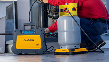
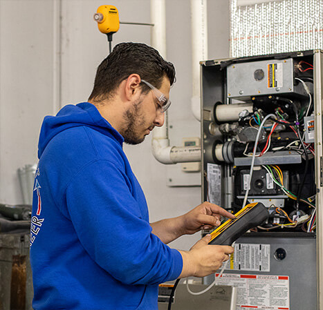
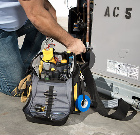
The analog gauge sets are built for HVACR system diagnostics, refrigerant recovery, pressure testing, and charging. They measure system pressure and saturation temperature to help technicians verify performance and diagnose refrigerant issues.
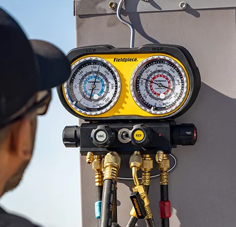
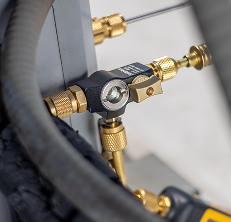
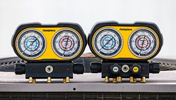
Each gauge set features a rubberized protective housing built to withstand jobsite use and service van wear. Both the 3-port and 4-port models include an integrated sight glass to view refrigerant flow and condition. A rotating pressure marker references the system target pressure or initial pressure during nitrogen pressure tests.
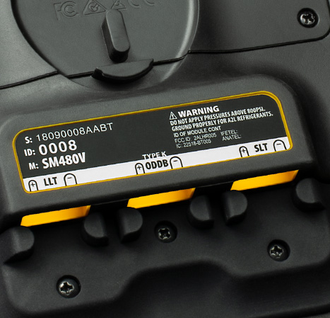
All gauges are compatible with A1, A2L, and A3 refrigerants. HVAC gauge sets include four refrigerant saturation temperature rings for R22, R32, R454B, and R410A. Refrigeration gauge sets support R134A, R404A, R407C, and R448A.
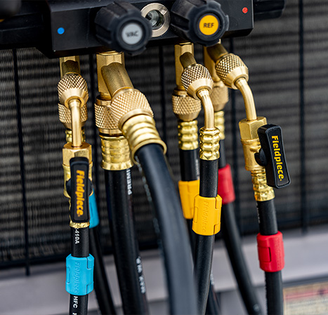
Additional design features include piston valves for precise control, high-grip valve knobs, swappable hose seats (1/4-inch standard, 5/16-inch optional), and a rotating hanging hook that folds into the housing.
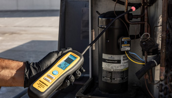
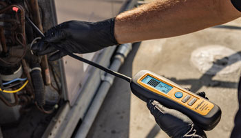
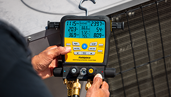
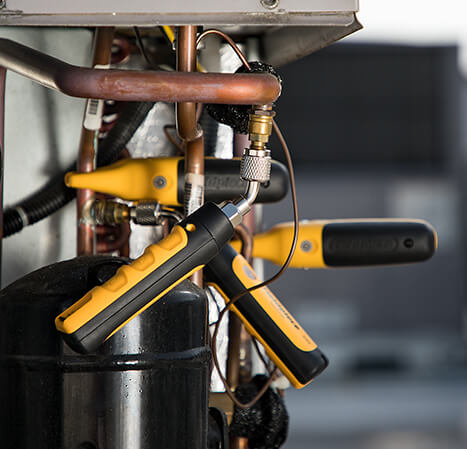
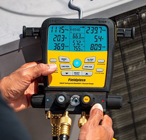
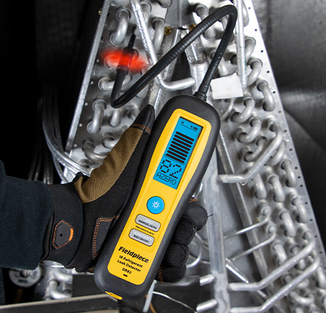
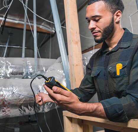
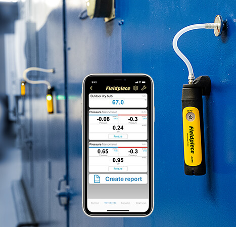
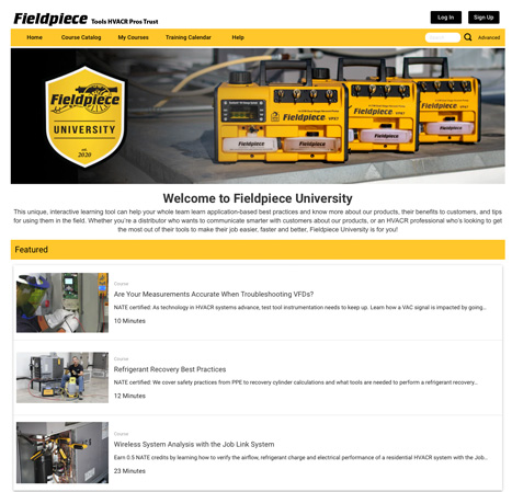
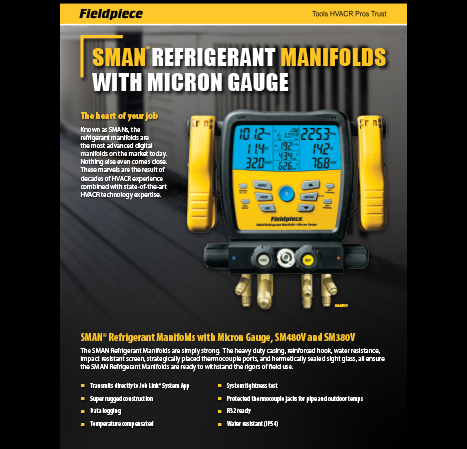
Digital refrigerant gauges, such as the SMAN® manifold, have transformed HVACR diagnostics, while wireless probes provide a fast, full system snapshot with measurements right where techs need them. Still, analog gauges remain a trusted tool and industry standard.
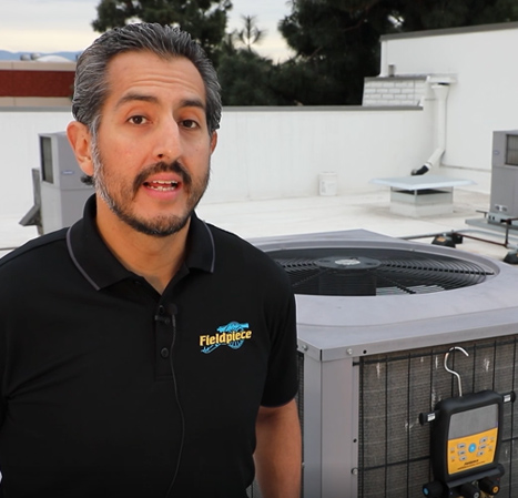
“Technicians learn on analog gauges, and many continue to use them throughout their careers,” said Craig Rodriguez, Vice President of Commercial at Fieldpiece Instruments. “We support all approaches to refrigerant diagnostics – analog gauges, digital manifolds, and wireless probes because each serves a purpose. Introducing Fieldpiece analog gauges ensures technicians can choose the right tool for the job, without compromise.”
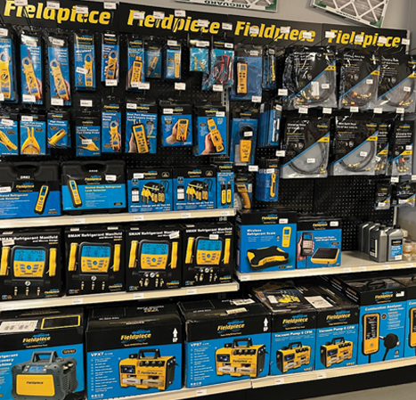
The new analog gauge sets are available now through authorized Fieldpiece distributors. For more information, visit www.fieldpiece.com or contact a local Fieldpiece representative.
ABOUT FIELDPIECE: Fieldpiece Instruments designs tools for HVACR professionals, empowering them to work easier, faster, and better. From precision measurement to advanced wireless systems, every Fieldpiece product is built to boost efficiency, accuracy, and performance in the field. Trusted by technicians worldwide, Fieldpiece is dedicated to advancing HVACR technology and supporting the pros who keep our world comfortable. Discover more at fieldpiece.com, and follow Fieldpiece on Facebook, Instagram, YouTube, and LinkedIn.