- Merchandise Shop
- Where to Buy
-

 English


 English
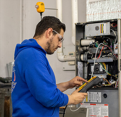
The next time you’re on a service call, the technology built-into your Fieldpiece wireless tools can make your time as efficient as possible. To make the most of that technology, here are a few steps to consider following:
Using wireless tools makes the troubleshooting process easier, faster and better but before we begin, it’s important to clearly understand the problem so we can determine what analysis needs to be performed. To do that, use your most important tool: Your ears. Often, when a customer is asked what’s wrong with their system, we hear: “It doesn’t work.” We know that answer doesn’t get us any closer to finding the actual problem, so it’s time to play detective.
The customer doesn’t need to be an expert in HVACR to help. But it helps to ask the right questions that may lead to finding the problem. Consider questions like: Does the system turn on? Do you hear any strange noises when it’s running? Does the system blow cold air? Does the system blow any air at all?
Let the customer speak and listen to what they say. The more useful information we gather from the customer up front, the better able and faster you’ll be to figure out the issue.
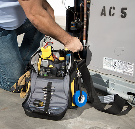
Once you’ve asked the right questions and begin to understand the problem, it’s time to get to work figuring out the issue. Based on what you got from the customer, you should now have a better idea of what could be causing the problem.
If the system turns on, it’s a good idea to begin with simple, quick visual inspections of the system. These include making sure the return air filter is clean, checking the outdoor unit for excessive debris that may be restricting airflow and using your hand to see if cold air is blowing from the supply vents. These quick and easy to perform checks help eliminate some possible problems right from the start.
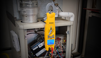
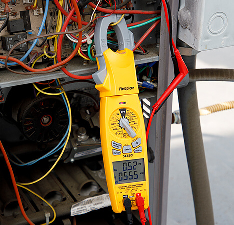
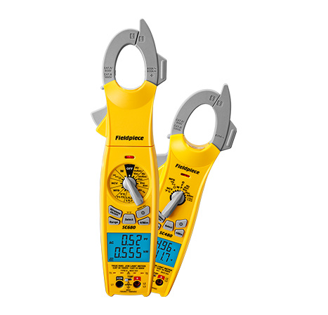
If the system doesn’t turn on, the issue more than likely is electrical. Use the Fieldpiece Wireless Clamp Meters, SC480 and SC680 to take voltage measurements at the thermostat and the outdoor unit. Also, be sure to check the fuses. This should be a good indication if there is an electrical issue with the system.
Here are some of the main tests typically run to fully understand system performance. First, you’ll want to do an airflow check, then check the refrigerant charge.
Checking Airflow via Temperature
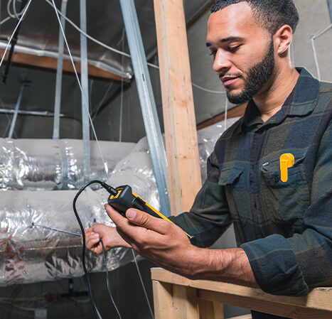
It’s often a good idea to start with airflow. After all, airflow is everything. First, use the Job Link® System Flex Psychrometer Probes®, JL3RH, to measure the Delta T. Attach one of the two JL3RH probes on the return side of the evaporator and the other on the supply side. This helps to understand the heat transfer that’s happening across the evaporator. When measuring this, look for a Delta T around 20 Fo. While this is a good rule of thumb, it’s a good idea to verify the manufacturer’s specs for their ideal Delta T.
If there is a low Delta T, it doesn’t necessarily mean there’s definitively an airflow problem. A low value could also come from a refrigerant charge issue so it’s important to check both airflow and refrigerant charge.
Checking the TESP
To further understand the airflow, measure the Total External Static Pressure (TESP) across the air handler.
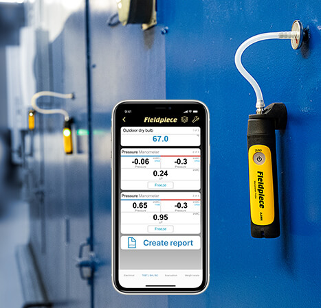
To measure this, use the Dual Port Manometer Kit, JL3KM2. When placing these probes around the air handler, check with the manufacturer’s recommendations. However, one probe should be positioned to measure static pressure before the air handler and one to measure static pressure after the air handler. Point the tips of the static pressure probe into the airflow. The JL3KM2 static pressure probes are designed with a red arrow on the magnetic base of the probe to ensure it’s pointed in the correct direction. Before inserting the probes into the unit, make sure to zero out the manometers – this helps get the most accurate measurement.
Once the data is acquired, the Job Link® App takes both static pressure measurements and automatically calculates the TESP. Compare this to the manufacturer’s max static pressure specifications. If the TESP is higher, there’s probably resistance to the airflow like a dirty return air filter, leaks in the ductwork, improper fan settings or poorly designed ducts. Examine all of these to determine what’s making the system perform poorly.
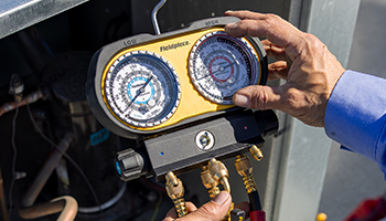
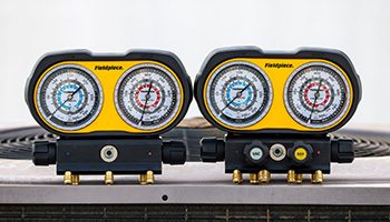
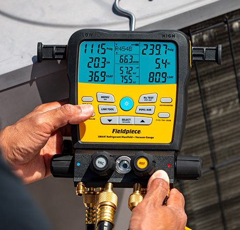
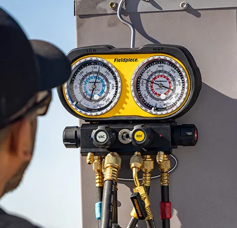
Checking the Superheat and Subcooling
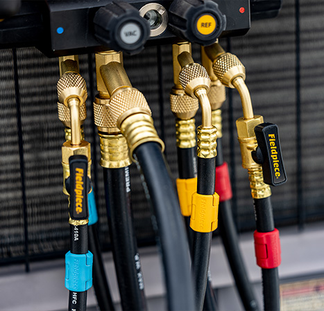
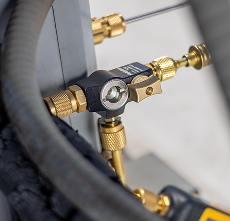
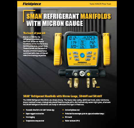
After checking the airflow, it’s a good idea to move on to the refrigerant charge. Do this by measuring the system’s superheat and subcooling values. The SMAN Digital Manifold and the Job Link® Pressure Probes and Pipe Clamps are specifically designed to capture these readings and compute the correct values. When the superheat and subcooling are measured you have better insight whether the system has the correct amount of refrigerant.
Since these levels can also be affected by improper airflow, measure both the airflow performance and refrigerant charge at the same time. This helps see the whole picture and create a more accurate diagnosis of the system.
Improving airflow.
If it’s determined that airflow is the culprit, make the necessary adjustments to dial in the airflow. Start with cleaning or replacing all air filters, cleaning fans, fixing duct leakages, and adjusting fan speed as needed. Check with the system manufacturer to determine ideal fan settings.
Recharging the system.
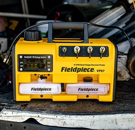
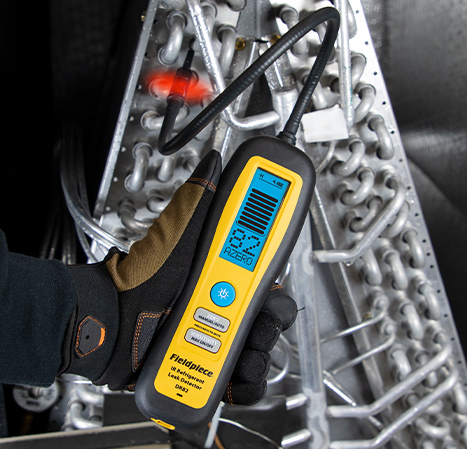
If it’s determined the refrigerant charge is low, it’s important to find out why. Use a reliable refrigerant leak detector to inspect the system for leaks. If found, responsibly recover the refrigerant as needed and perform the repair. Once complete, perform a proper system evacuation to remove all moisture and non-condensables from the system before recharging with the correct amount of refrigerant.
Know you’re right
While measuring and testing the system with wireless tools, it’s okay to leave these in place as adjustments are made. Then after service is complete, re-run the TESP and Delta T tests to see if the system is performing better. Be sure to also measure the subcooling and superheat to check that the refrigerant charge is correct. Since these are wireless tools, there is no wasted time re-attaching the meters and gauges. You can leave them in place as you work. Also, as you move around the system throughout the service call, you can recheck these values to gain a real-time picture of the improving health of the system.
Call-out #1
Measuring Real-Time Power Consumption
The Fieldpiece Wireless Clamp Meters, SC480 and SC680 offer a unique tool while on service calls – showing customers how much energy their system is consuming. Most other meters on the market don’t have this feature. First, at the outdoor unit attach test leads to measure incoming VAC on the L1 and L2 terminals. Then use the amp clamp on the L1 or L2 wire. Set the dial to the W position and the meter displays real-time power consumption in kW.
Before performing the service call, measure the power consumption. And then, do the same at the end. Show the customer a before and after power consumption comparison to validate the work completed and to build trust.
Call-out #2
Rapid Rail® Sensor Technology
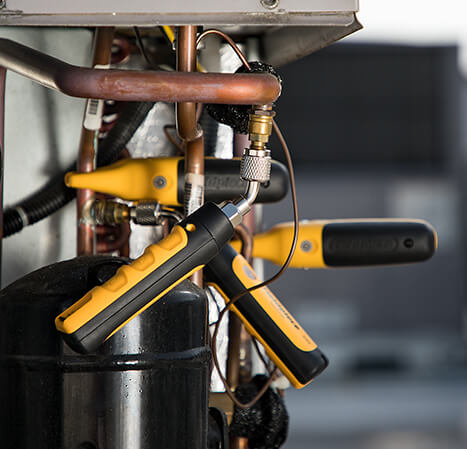
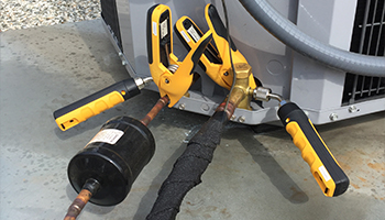
The Job Link® System Pipe Clamps JL3PC and the large JL3LC use revolutionary, patented technology to measure temperatures in a pipe. It’s called Rapid Rail® Sensor Technology and it offers more accurate, faster readings. Since the copper of a pipe is electrically conductive, the Rapid Rail® Sensor uses the pipe itself to complete the sensor circuit and measure the temperature. This provides a more accurate and a more stabilized reading in just a few seconds and it isn’t affected by the ambient air conditions. This innovation saves time and is far more accurate than other pipe clamps.
Call-out #3
Testing Variable Frequency Drives (VFDs)
Many times when testing the electrical components of a newer system, you come across Variable Frequency Drives (VFDs). These are designed to be more energy efficient by ramping up and down based on the systems required load – instead of just running at either 100% or 0%. The SC680 and SC480 measure VFD voltage more accurately by filtering out the electrical noise that’s present on the exiting voltage signal. Other meters on the market not designed for VFDs can’t filter out the signal noise and won’t give an accurate reading.
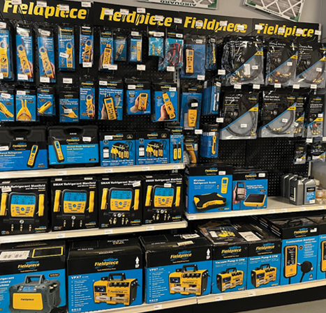
Contact Fieldpiece today to learn more about our wireless tools and improve your productivity on the job.