


Introduction
As HVACR technicians, job number one is ensuring the comfort of the customer. For an HVACR system, it is effective heat transfer and efficient conditioning in all intended zones of the system. Efficient distribution of airflow in both residential and commercial spaces greatly impacts the ability of the system to effectively heat or cool the intended zones. Proper airflow across an evaporator coil and throughout the ductwork can efficiently condition a space and keep it comfortable, while improper airflow can lead to some rooms struggling to stay cool or even reach the target temperature. In situations like this, the problem at hand may be improper air balancing.
What is Air Balancing?
In short, air balancing is the process of testing and adjusting your air conditioning system to deliver the right amount of air to the zones of a given space. Proper air balancing ensures that each room or zone receives the correct amount of air, maintaining consistent temperatures and improving system efficiency. It is a critical step in both the installation of new systems and the maintenance of existing ones to ensure optimal performance and comfort.
Signs of Improper Air Balancing
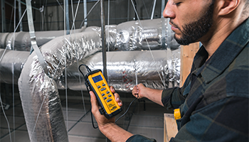
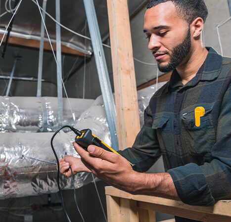
When a single system is effective in some zones, and not others, a technician may need to conduct air balancing. This starts with some simple diagnostics of the zones themselves. Using an IR thermometer or psychrometer, conduct a walkaround test and read temperatures from all registers in each space. Record temperatures manually, or if using psychrometer probes like Fieldpiece’s JL3RH Job Link® system probes, view all live temperature readings at once on the Job Link® System App. Once the underperforming zones are identified, move on to troubleshooting.
Conducting Air Balancing
Once the problematic zones are identified, first check to see if there are dampers, and if they are properly positioned. Manual dampers may have been closed off halting airflow, or electronic dampers may be malfunctioning to improperly manipulate airflow. Adjust all dampers while monitoring temperature from registers in problem zones to see if performance improves. If dampers are all properly set and the problem zones remain unchanged, an inspection of equipment CFM and static pressure may be necessary.
To check equipment CFM, technicians can use either an airflow capture hood, or an anemometer like the Fieldpiece STA2 Hot Wire Anemometer to conduct a traverse. Conduct a traverse in the appropriate location for the given system, for most residential systems this will be as close to the return or return plenum as possible. Run the system for at least 15 minutes to allow the system to stabilize. If using an anemometer, conduct a traverse by first setting the anemometer to the appropriate return size, and record airflow readings across the return space. For proper measurement points for rectangular, square and round ducts, see the Fieldpiece STA2 Operator’s Manual. In a balanced system, total return CFM should equal total Supply CFM. Compare measured CFM to manufacturer specifications for the given equipment to see if it falls within the target values.
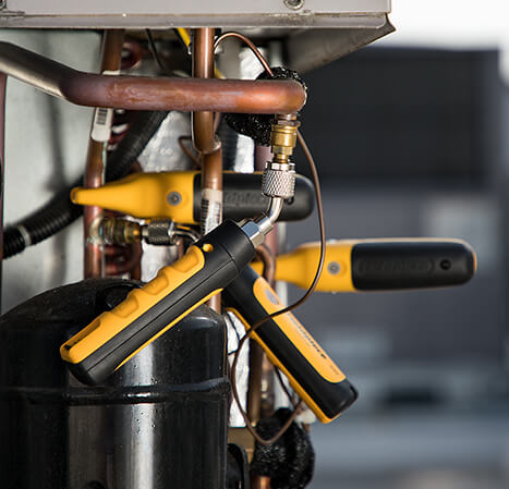
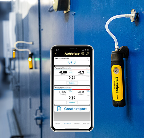
To check system static pressure, use a dual port manometer or wireless manometer probes like the Fieldpiece JL3KM2with static pressure tips and flexible tubing. Zero the manometer while in ambient pressure with any tubing or probes attached. Specific placements will vary depending on your equipment, but in general target manometer placement will be before the blower and after the coil or heat exchanger. Be sure to point the static pressure probe into the direction of the airflow. Calculate the total external static pressure (or TESP) by adding the return and supply readings. Comparing the measured TESP to the equipment’s design specifications can indicate static pressure issues.
If CFM is found to be lower than the manufacturer specifications, or static pressure is found to be too high, several troubleshooting steps can be taken.
Troubleshooting Tips
Check the return filter to ensure it is free of obstructions such as furniture or other items that may restrict airflow. Next, inspect the blower and make sure it is free of buildup and set to the appropriate speed, or setting for variable speed blowers. Inspect the evaporator coil and clean if required. Lastly, check the actual sizing of the return and supply plenum, as improper installation or obstruction may be constricting airflow. This applies to ducting throughout the system as well, so check for inefficient installation and leaks. Ensuring each of these possible points of impedance is addressed can greatly improve overall system airflow and air balancing.
Keep in mind that the equipment in an HVACR system is only part of the equation. Other considerations to customer comfort should include the structure of the home and other additional factors. These may include customer preference, room orientation and ceiling height, points of ingress and egress such as door cut and clearance, insulation, and the orientation of the structure itself as zones in direct contact with sunlight will require additional cooling.
Systems that meet all manufacturer specifications and have no discernable inefficiencies present may still struggle to properly condition a given space. Under more extreme circumstances, an undersized system may have been installed. Requirements for system size may vary regionally, but in general there should be 1 ton of system for every 400-500 square feet of conditioned space. While it may be more common for an installer to oversize a system to ensure enough heat transfer, system size is a critical factor that should not be overlooked.
Final Thoughts
Airflow is a critical aspect of every HVACR system. Both airflow across the evaporator coil and airflow through the ductwork itself are essential for effective air conditioning in a given space. When airflow is imbalanced, comfort in individual zones can suffer. Proper air balancing can greatly increase effective conditioning and comfort in all zones, making troubleshooting and finding solutions yet another essential tool in a technician’s toolbelt.